


Making of Termitary House
Pixelpark‘s ‘Termitary House’ visuals, inspired by the real ‘Termitary House’ in Thanh Khê District, Da Nang, Vietnam designed by Tropical Space Studio, awarded them Best Visualization of the Week NO. 49/2015 for a remarkable CG remake and level of details they went into remaking the house signature feature – The Bricks. Follow this article as they describe the process of creating these highly photorealistic visuals using 3dsmax, GrowFX, V-Ray and just a bit of postwork. Enjoy!
Introduction
In the spare time among our works we engage ourselves in some in-house projects, each time trying to realize something new. It’s a challenge and we must face new tools or techniques we’ve never used before. Being able to manage them gives us great satisfaction and allow us to grow in terms of know-how and experience.
As usual, we searched some interesting project on Archdaily.com, and we found this beautiful project from Tropical Space Studio.
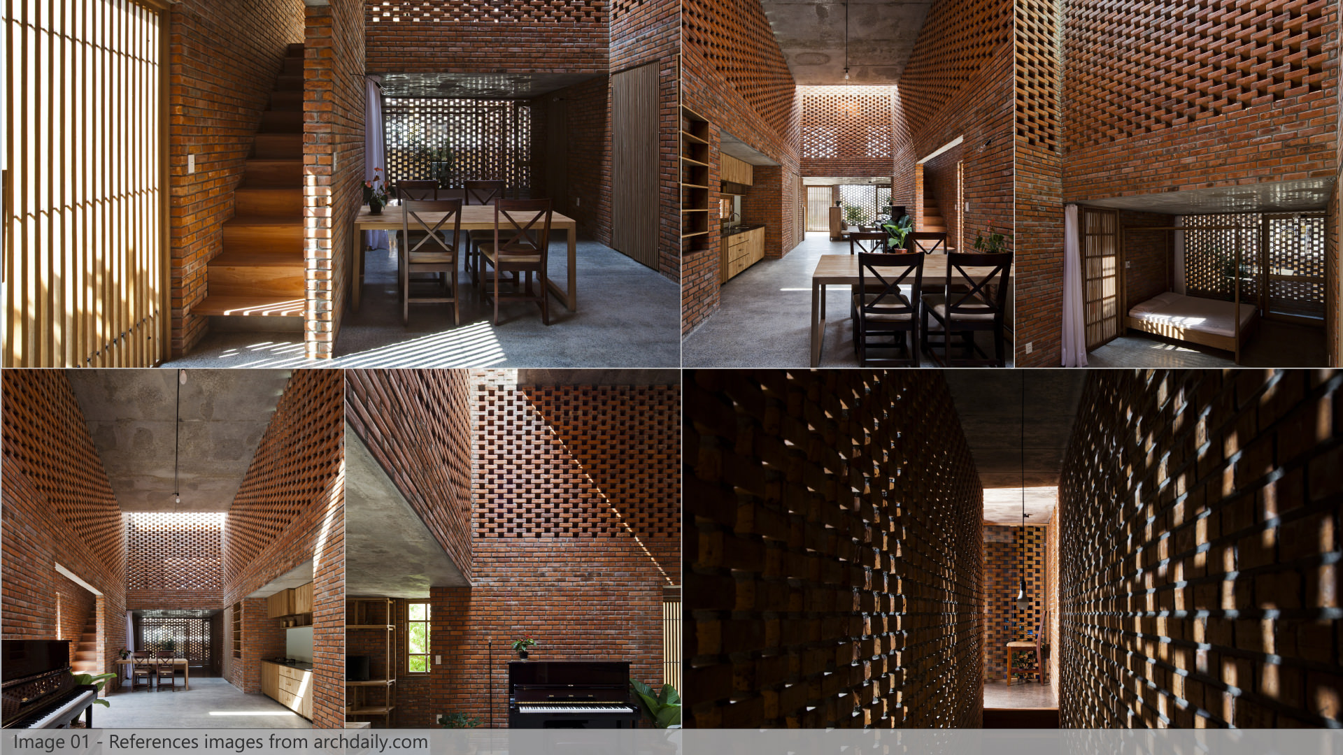
Termitary House is a small building located in ThanhKhê District, Da Nang, Vietnam. We really loved it, we found it very unusual and we strongly appreciate the global mood of the house.
Early Tests
From the beginning, we had one word in our minds that kept resonating during the entire process of crafting this project – BRICKS!
They were everywhere in this house, and no matter the reference pictures we looked at, they played the main part. Therefore, we realized that the first step before approaching this project was to decide how to create the bricks, keeping in mind that there would have been bricks in the background and also in the very foreground. So we definitely needed to create them with very high levels of detail.
After few types of research and tests we immediately decided not to use textures with displacement because :
- We didn’t want to see any tiling (and even with large maps, there would have been images where the repetition of the pattern would have been visible).
- Displacement wouldn’t have worked properly on walls heads and corners.
- We wanted to be free to add several layers of dirt or color correction on the bricks material.
- Using bitmaps we wouldn’t have been able to create the walls with gaps among the bricks (and there were lots of these “termitary” walls).
So we started thinking about using 3d models of single bricks and place them with the right pattern, but at the same time including some kind of variations and imperfections. Obviously we didn’t want to manually place all the bricks. We decided on using the Multiscatter plugin, thinking we could use its “regular distribution” option to achieve our goal. A short study process have been necessary for corners areas, but in the end the results were convincing so we started building the house… brick by brick, literally!
3D Modeling
Structure
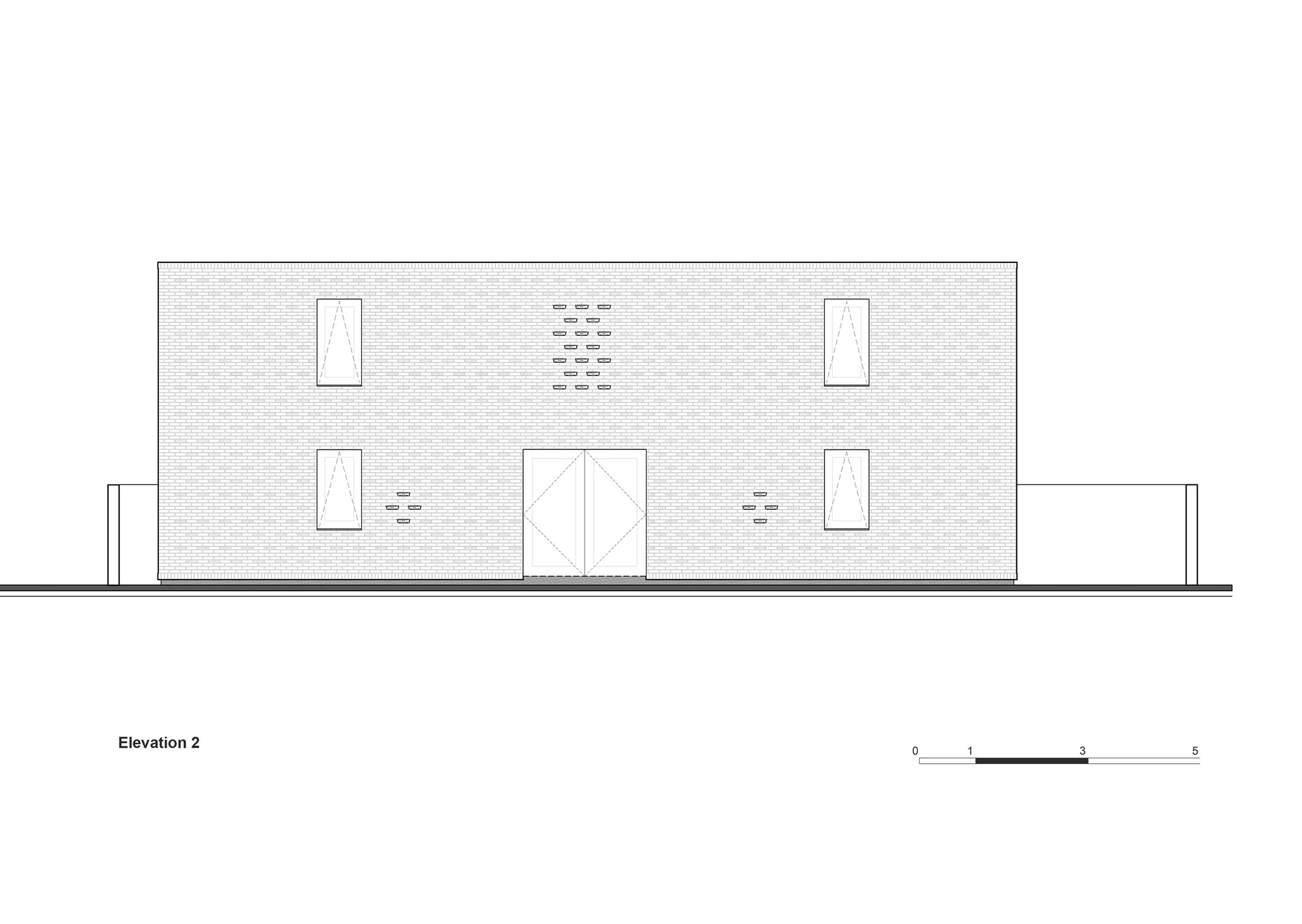
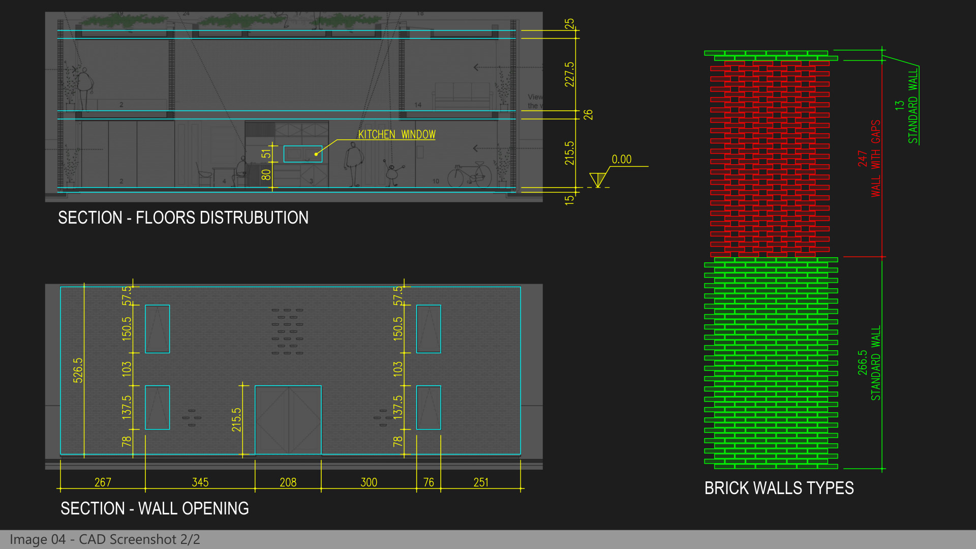
We started from AutoCAD, using plans and sections from Archdaily reference pictures to draw a base version of the house. This step has been very important. Bricks were the base unit of the whole structure, and with AutoCAD, we’ve been able to precisely design all the openings on the walls and the height of the levels with the correct dimensions in relation with the bricks.
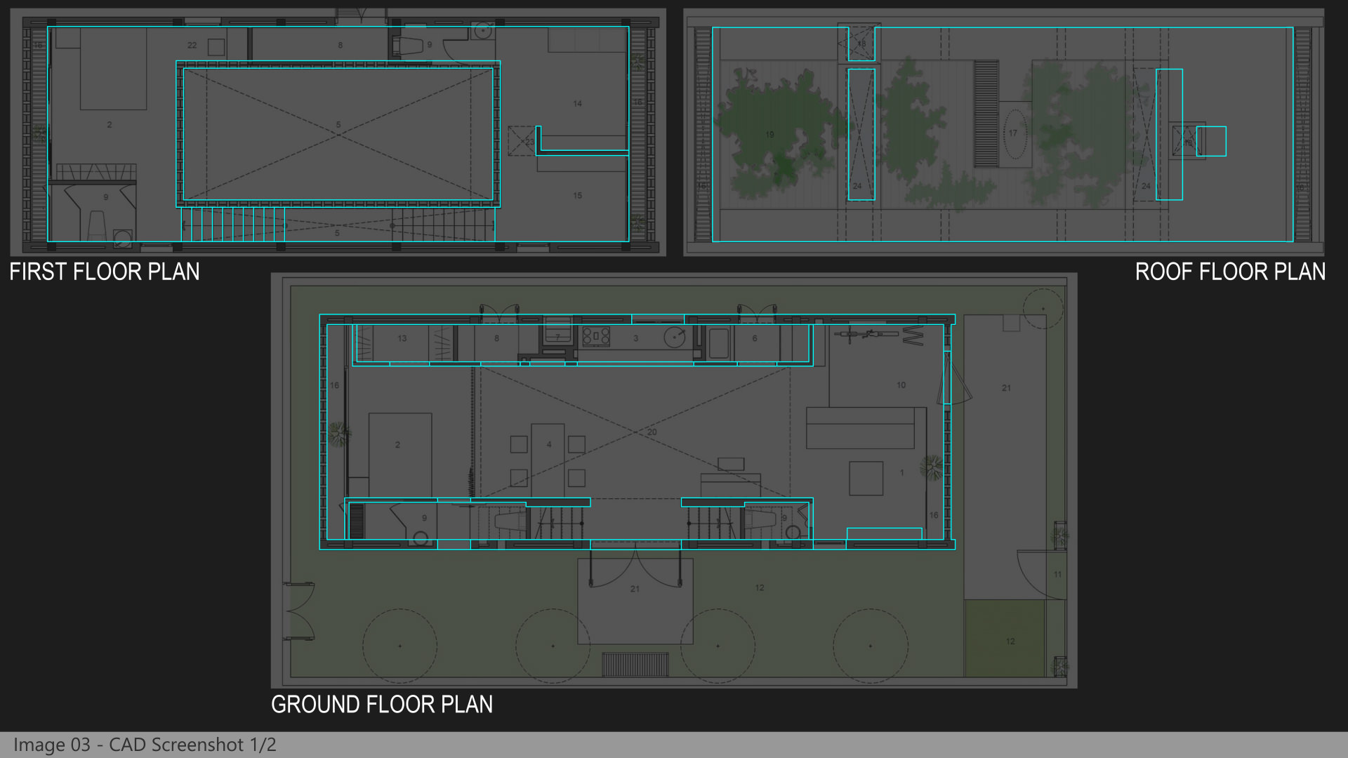
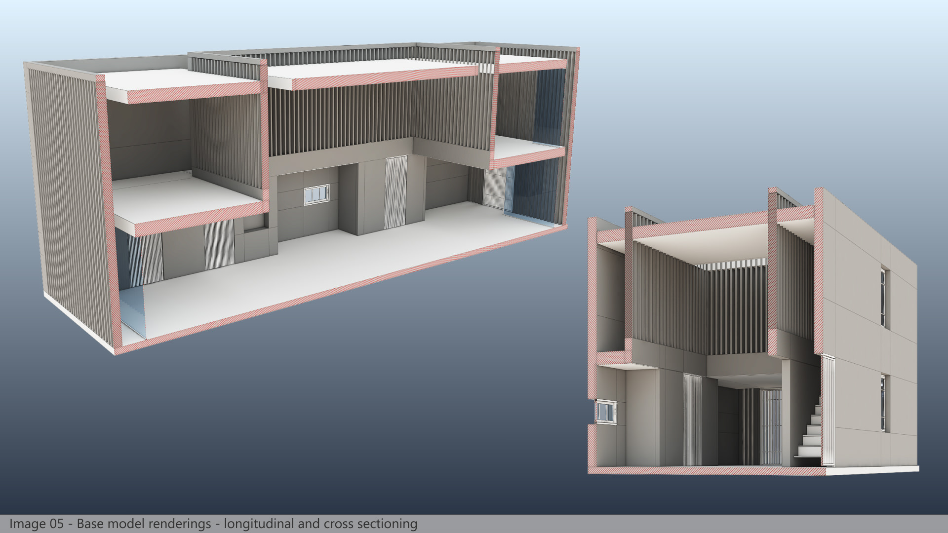
We used the DWG files as a blueprint inside 3ds max to create the final model. At this stage for the walls we simply built boxes representing the mortar, i.e. one centimeter thinner than the final walls thickness that includes the bricks.
The Bricks
They have really been the heart of this project, with the first step being the creation of single bricks meshes.
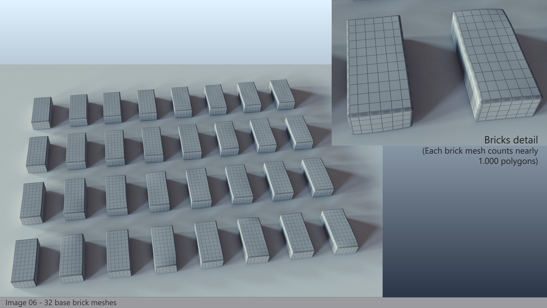
We created 8 different versions, with slight variations in the base geometry obtained via modifiers (like noise and FFD) and/or manual editing of the editable poly objects.
Next, from each mesh, we generated 4 variations simply rotating them 90° around each axis (this is because Multiscatter doesn’t allow random rotation with fixed increments). In this way, our Multiscatter walls could rely on 32 different meshes.
Finally, we converted each mesh into a V-Ray Proxy for better RAM usage (every brick mesh had about 1000 polygons, and we were planning to scatter lots of them).
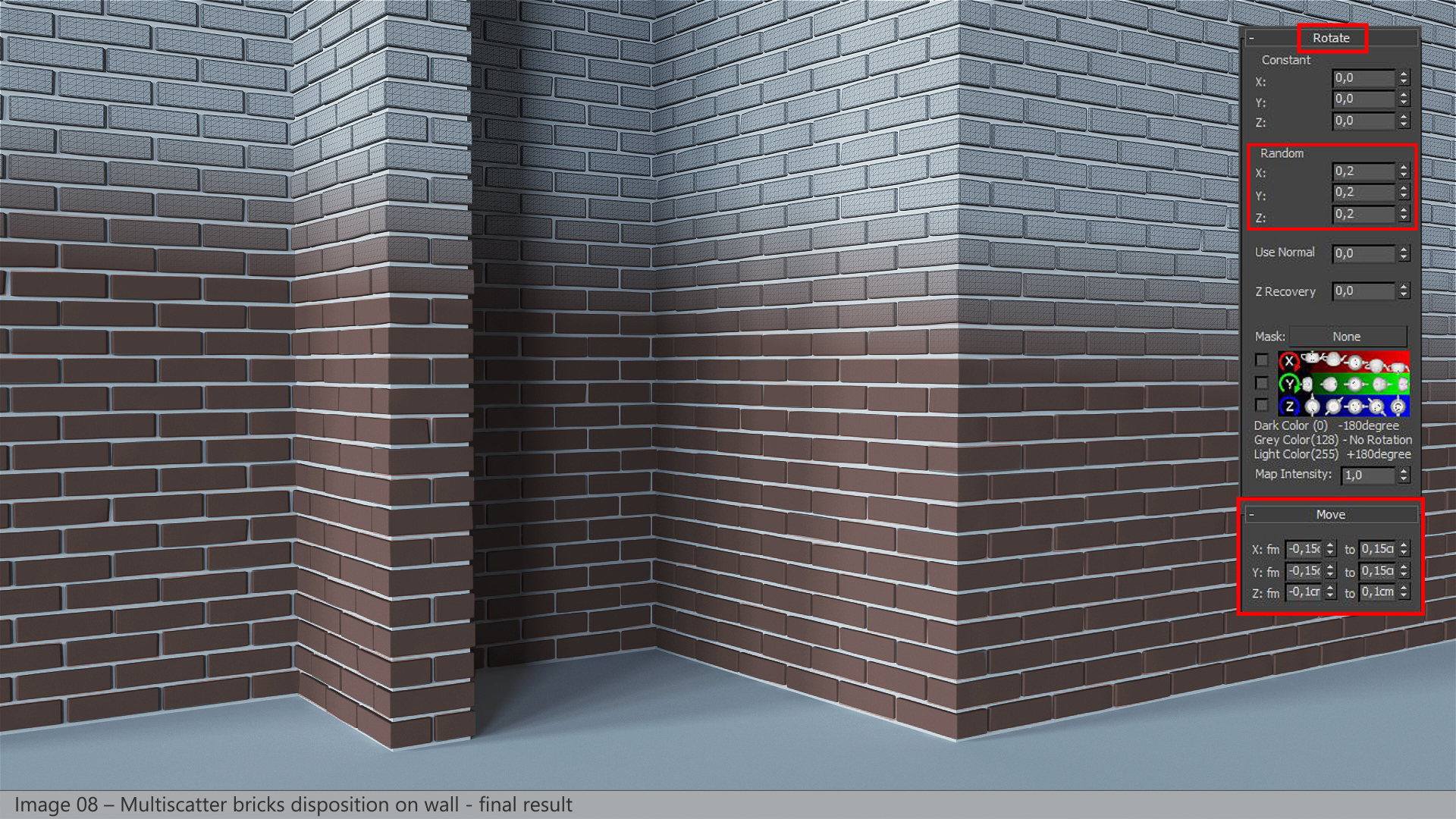
For each wall to populate with bricks we set up a Multiscatter object using the surface distribution mode on a non-renderable plane, disposed so that bricks were protruding 1 cm from the mortar mesh. To obtain the correct brick distribution we properly set up a UVW map modifier applied on the distribution plane.
For the “termitary walls” we followed the same process, simply modifying the parameters of the UVW map modifiers applied to the distribution surfaces of the Multiscatter objects. This process has been extended to all the walls, including the wall heads, taking particular care of corners where two different Multiscatter were intersecting.
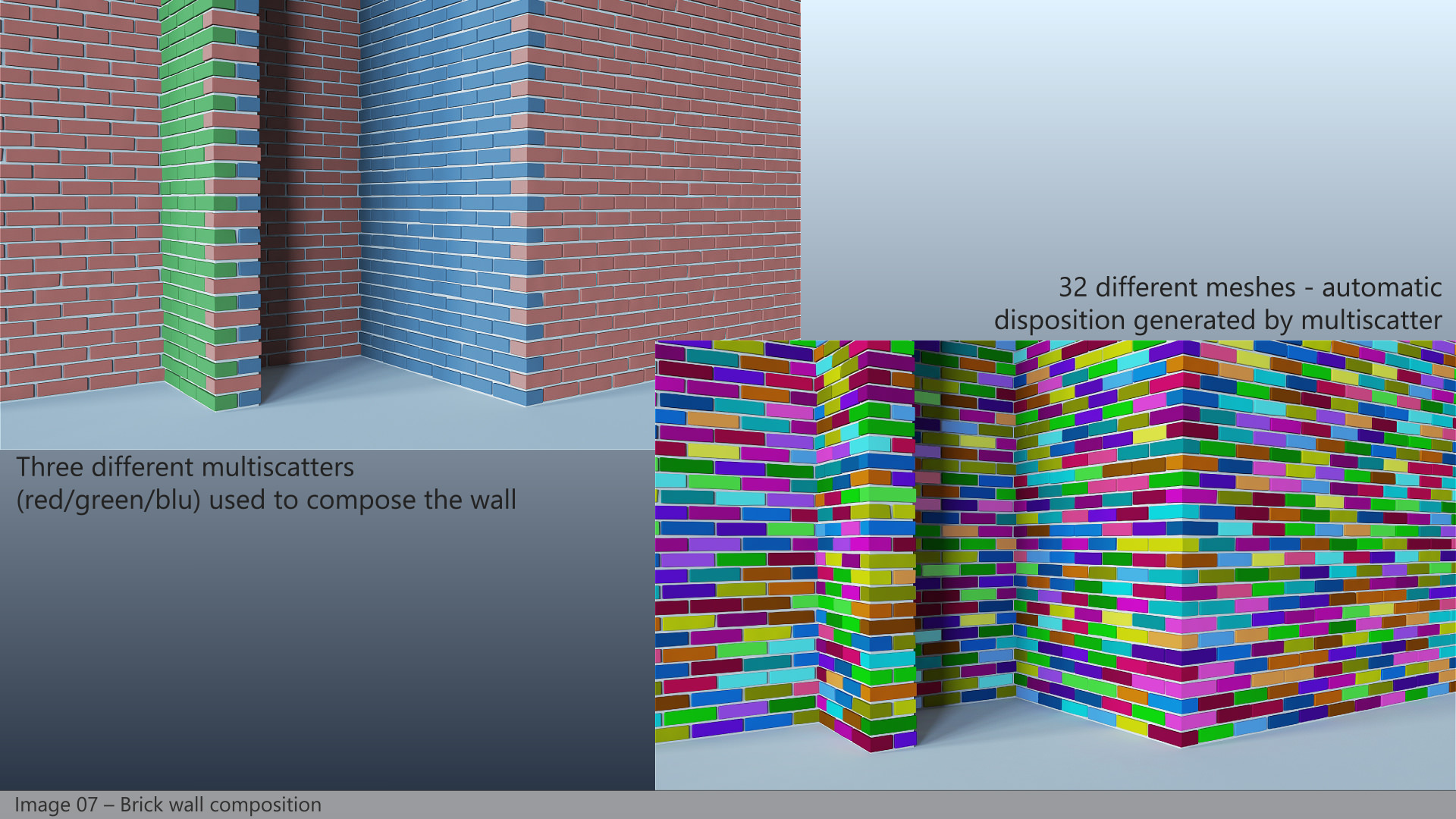
Finally, we have found the right level of imperfection of the bricks distribution using random position and rotation inside Multiscatter. In the end, to build all our walls, we have used 19 different Multiscatter objects, with about 27,000 (!!!) single bricks scattered all around the house.
Furniture & Objects
As usual, we tried to 3d model everything in detail, even for the objects far away from the cameras. We believe this helps the final pictures to look more realistic (maybe there will be some rounded edges that produce a specular highlight in the distance, you never know could be the difference), and we can also re-use the models in future projects, without worrying if they’re detailed enough.
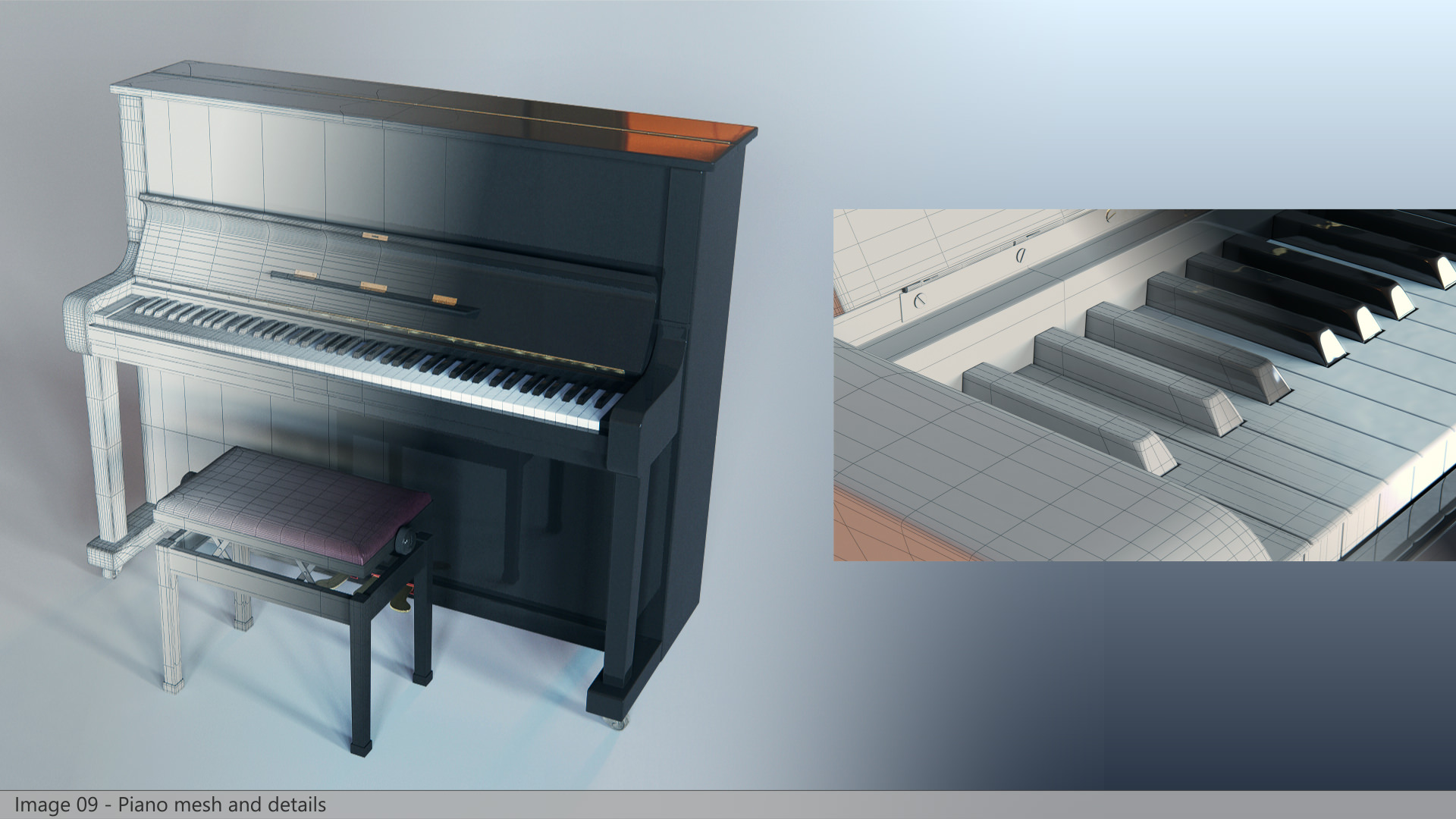
Most of the furniture were very simple while other objects have required some more efforts, for example, the piano. We modeled it from scratch using various reference pictures from the web to design all the small details. Matteo from Pixelpark modeled the piano. He’s also a musician, playing the piano and owns one at home… this really helped a lot!
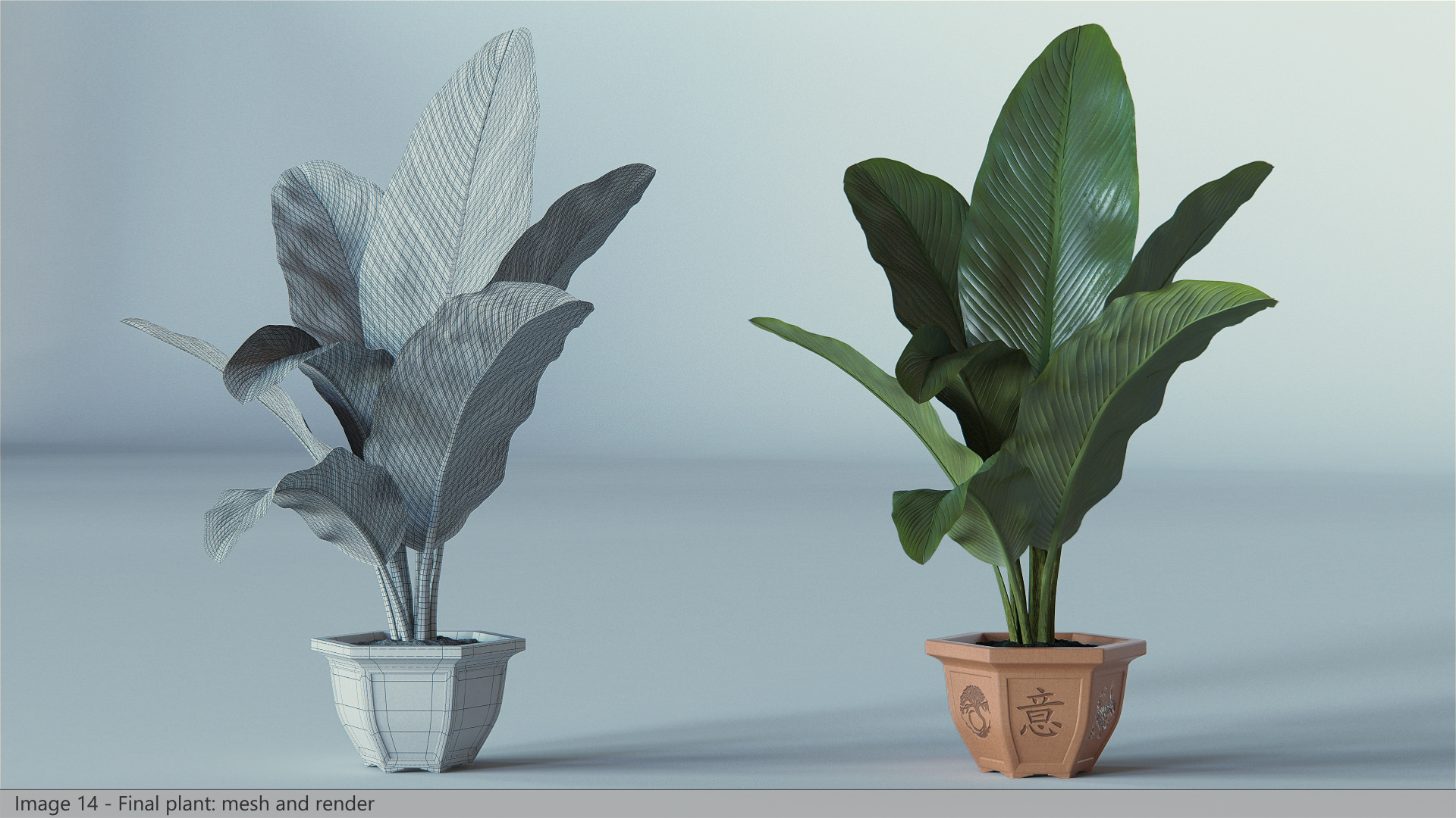
There were also lots of plants in the house which we wanted to maintain the tropical typology feel to them because of the location of the building. We absolutely didn’t want to use external pre-built 3d models (anyway we couldn’t find anything with such large leaves as the original plants). So we built our own models, using the GrowFX plugin and instanced geometry for the leaves. This allowed us to generate the different versions of the same plant with a few clicks.
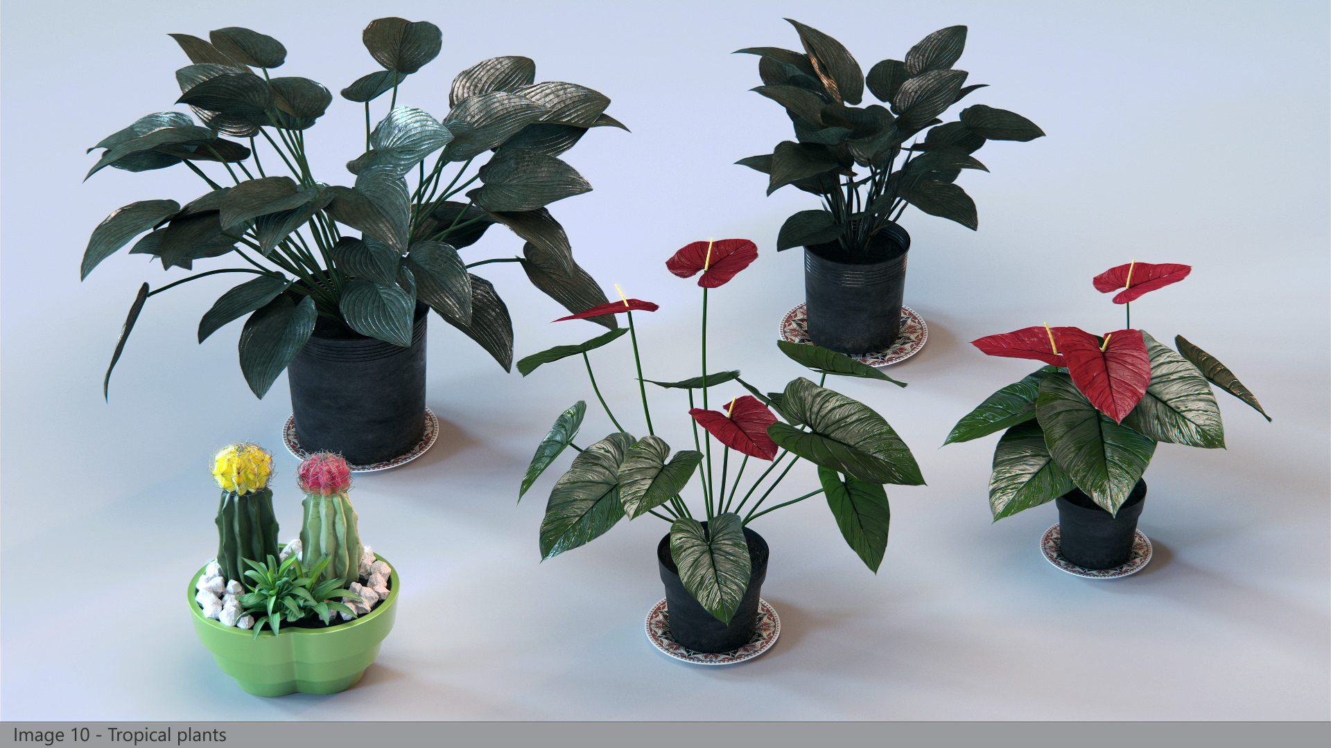
The big plant near the piano has been the most tricky one to create because it was the most visible one in the images and so it required high levels of detail.
First, we searched and found the right leaf texture on CGtextures.com, then we processed in photoshop to get the correct shape and to clean it up from some dirt that was in the picture. From the modified texture, we created diffuse, Opacity and Reflection textures with simple color corrections.
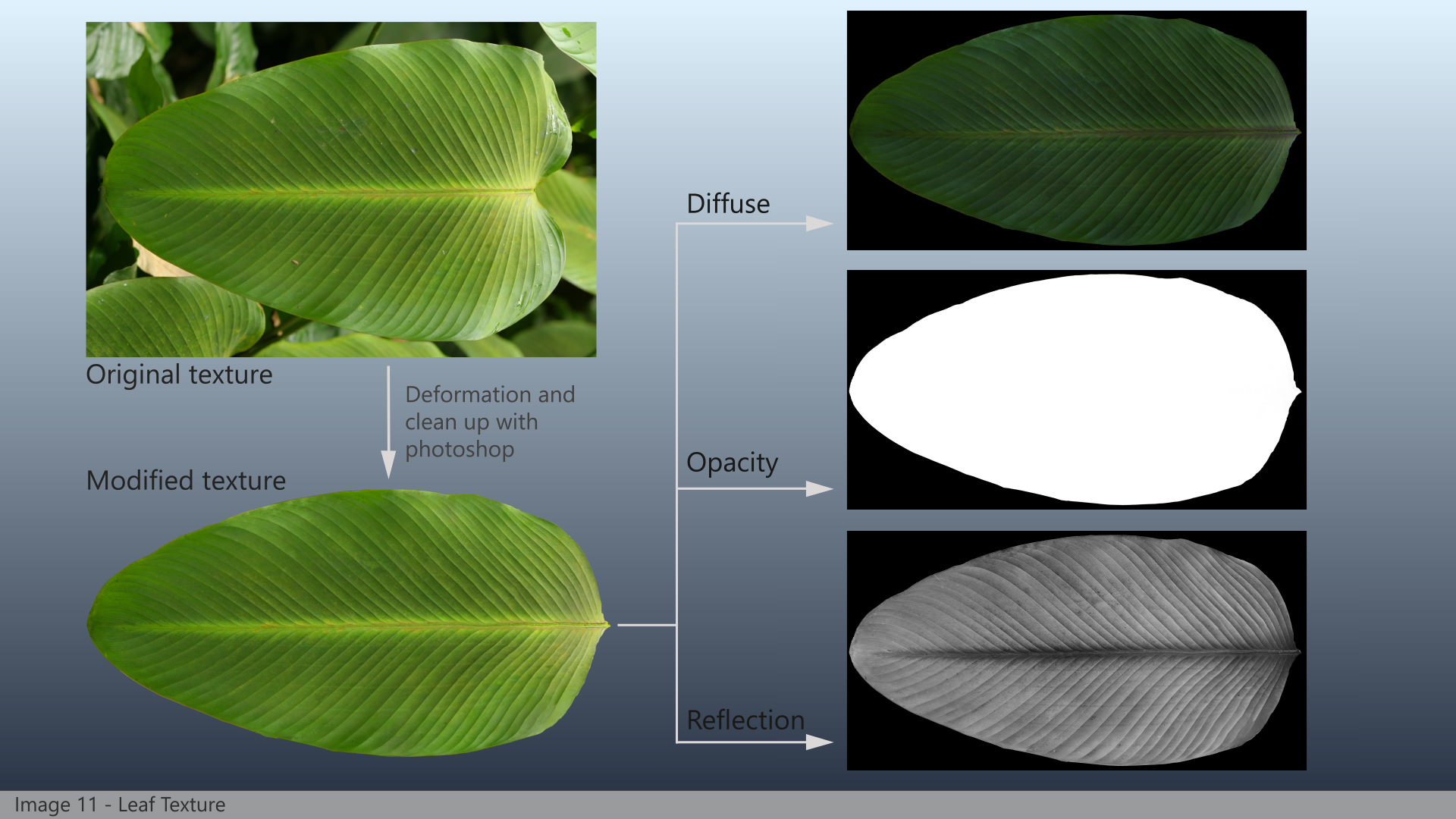
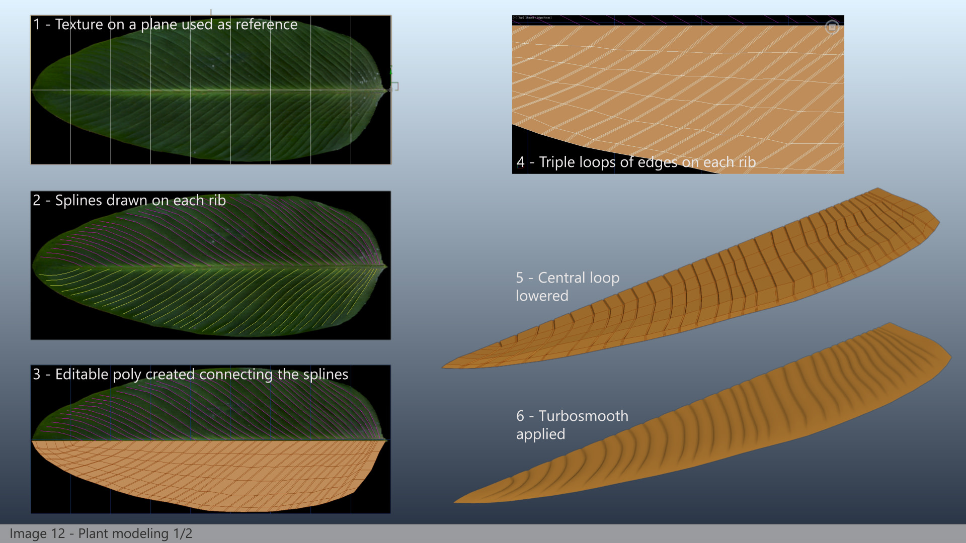
At this point, we used the texture as a reference in 3dsmax to model the correct geometry.
To do this we started from splines drawn following the single ribs of the leaf. We built each spline with the same number of vertices, in order to properly connect them together in an editable poly to create the base mesh. On each rib we placed three loops of edges, then we lowered the middle one and applied a turbosmooth modifier.
Once we created the first half of the leaf, we then made the second one with the same process (using the texture as a reference, the two halves were not the same!) and the central stem as well. Then we collapsed the three meshes together and applied various modifiers (wave, noise, twist and bend) to create a natural deformation.
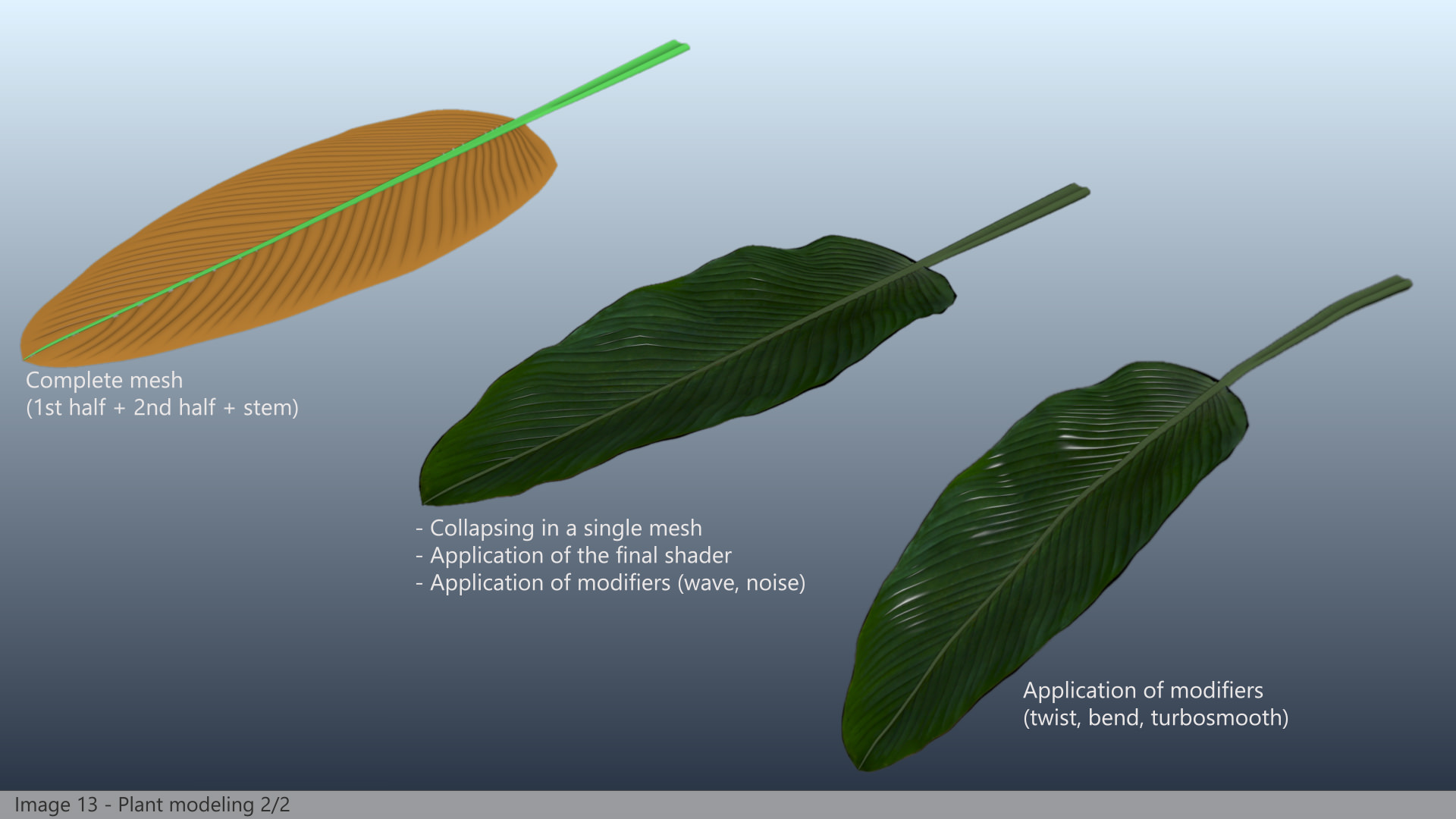
Lastly, we composed the final plant referencing 7 leaves and manually changing some modifiers value to get the desired look. We then added the pot and the soil, and we were done.
Camera & Lighting
When we work on such projects our goal is to create several images from the same scene, but often they could have different light conditions and/or different objects setup.
To simplify the workflow and to keep things well organized, instead of creating one camera for each final picture we prefer to use just one single camera for all the images (well, actually here we used two cameras… one for the horizontal images and one for the vertical ones).
To get the whole process working we simply animate the position of camera and target for each frame, along with other parameters like shutter speed or vertical shift.
In addition, we also animate other objects properties, i.e. lights intensity, sun position, and we also move some objects around to fit what we need to see in camera (we consider this process very similar to what professional photographers do when they prepare an interior set before taking final pictures).
With this setup all we have to do to switch among the different final images is simply slide the 3ds max timeline to the desired frame, without worrying about turning on and off some lights or manually hide certain objects or layers. We find this workflow extremely useful, and it also allows us to launch long rendering process for several images at once, without having to setup any batch process (simply say to max to render the frames from X to Y and let it work during the night.
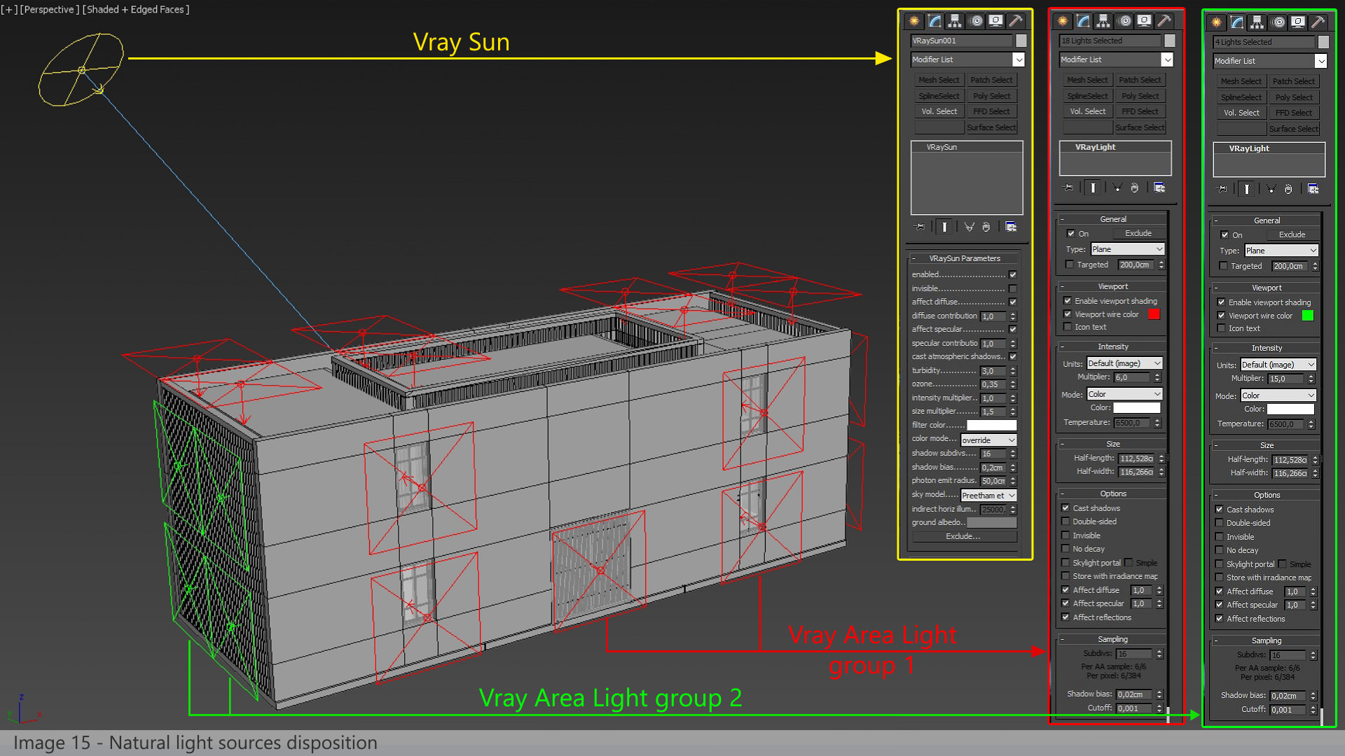
Once we had the cameras animated, it was time to set up the lighting. We planned to output 10 images, 8 with natural daylight illumination and 2 with artificial lights.
For daylight setup we used a V-Ray Sun along with V-Ray area lights positioned at windows and at ceiling openings. We grouped area lights in two different sets, to be able to adjust color and intensity separately to fit our needs in terms of quantity and color of light per image.
For the night-time setup, we animated the Sun and area lights intensity to 0 and added some V-Ray spherical lights, placing them where the reference pictures showed lamp bulbs. We did not boost these lights at this stage, we wanted to keep them with a lower intensity then the final one to adjust them in post (see post production chapter).
Texture & Materials
Materials done right are crucial for photorealism. In this project we haven’t used any particular tricks for any shaders, just the right combination of base textures for diffuse, reflection, glossiness, refraction and bump. The only “rule of thumb” we try to follow during the material creation process is that everything must be reflective and have dirt on it. This means starting with a diffuse texture, then add some dirt (based on masks or using VRayDirt texture), then make the shader reflective (using the correct textures for reflection and glossiness). Some bump and lots of rendering test and that’s all.
The only “secret” is to be patient and to take care of the details. It is a time-consuming part of the process because of the number of renderings we had to do (using high parameters) to visualize the final result.
The Bricks Shader
Again, we used great attention for the bricks materials. After the modeling step, we had a house built up with 32 different meshes randomly distributed by multiscatter. Always trying to keep things as simple as possible, we set up a unique material for all the bricks, with a base bare layer and many dirt layers on top of it, driven by b/w maps or VRayDirt maps. We kept the maps large enough to let us move the UVW map gizmo of the 32 single brick meshes, so to obtain 32 totally different bricks.
But after some tests we realized this was not enough to avoid repetitions, so we copied the 32 bricks and applied 32 more UVW to them. At the end of this process, we scattered 32 meshes but with 64 different materials applied.
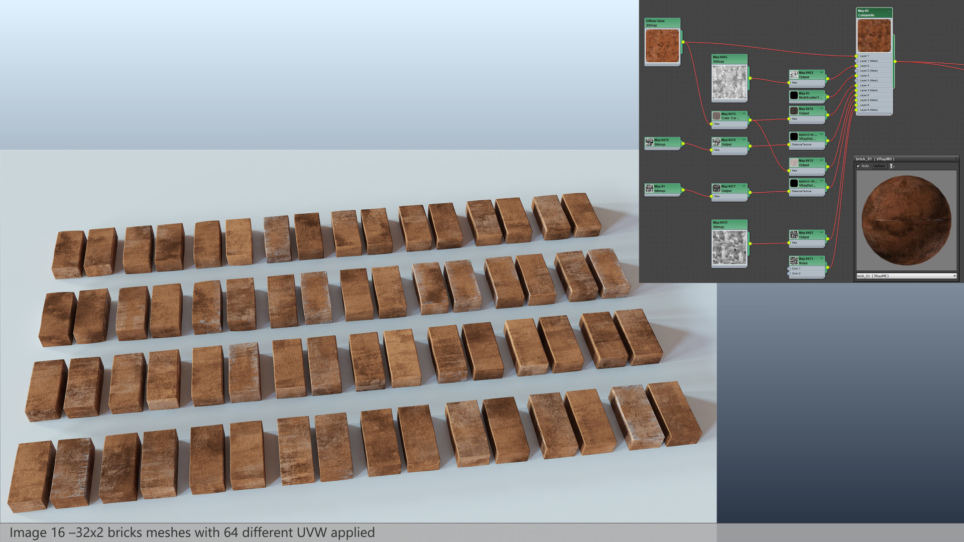
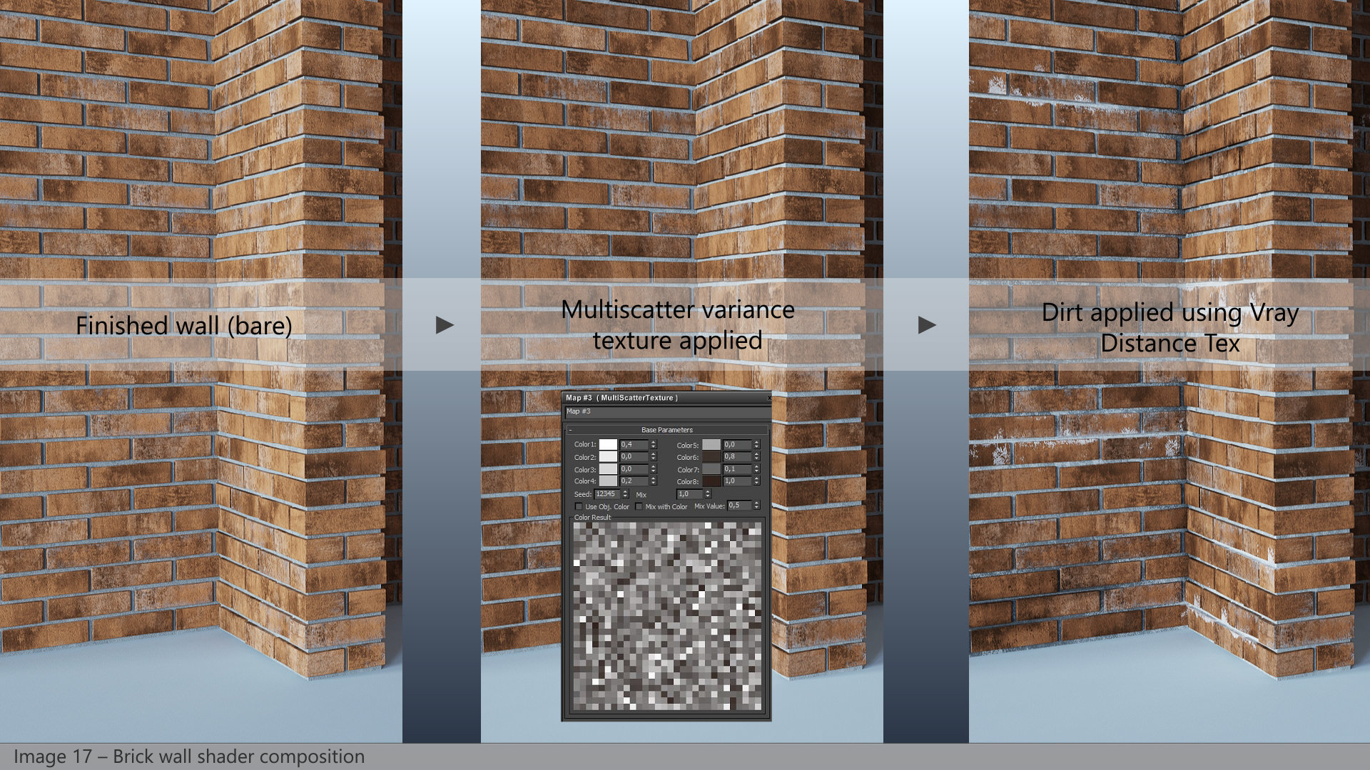
On top of it, Multiscatter gives the fantastic opportunity to use a Multiscatter Texture, to apply random variations to the meshes it scatters. This was added in the composite map of the diffuse, and finally, our brick wall was… built!
At this point we were really satisfied, but the walls of the reference pictures were… more real!
We still had to add local dirt, dirt, and more dirt! And this latter had to be something that affects whole groups of bricks, not just single bricks. For this task, we used VRayDistanceTex, to apply dirt based on the geometry of meshes or simple splines we place very freely and keep non-renderable.
The Concrete Ceiling Shader
One thing we try to do when we “copy” an existing architecture is to replicate as best as possible the details that make the subject unique and particular.
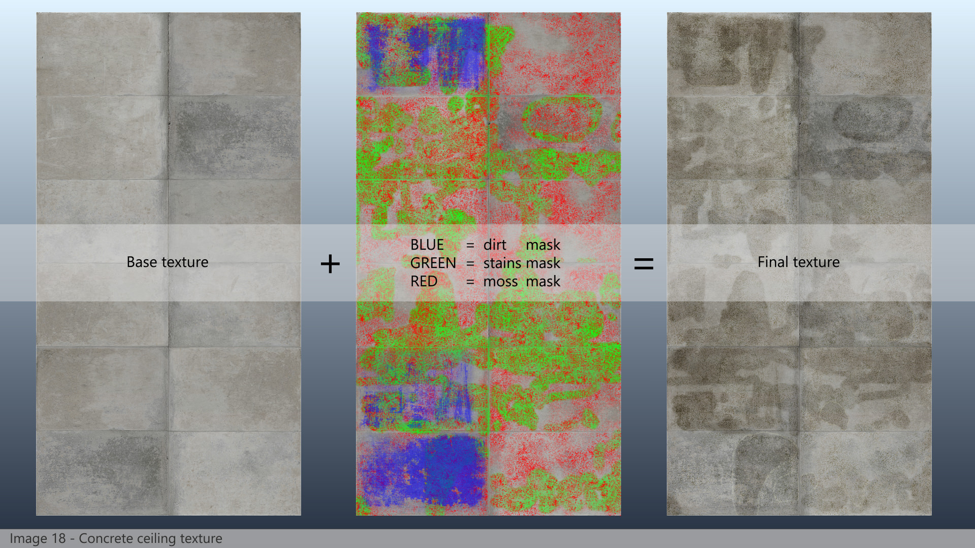
In this project, the ceiling texture was definitely one of these details. Obviously, we couldn’t think to find something even close to it on the web, so we built it on our own.
First we created a low-res version of the texture simply cropping and distorting the reference pictures, and giving it the correct aspect ratio. Then we created the whole hi-res texture in After Effects combining layers of bare concrete with other layers of dirt.
For this purpose, we manually painted masks conformed to the reference texture. From the final diffuse layer, we created the reflection, glossiness and bump maps adding some color correction and curves adjustment layers. The final shader was a V-Ray material with all the maps in the right slots.
More Shaders
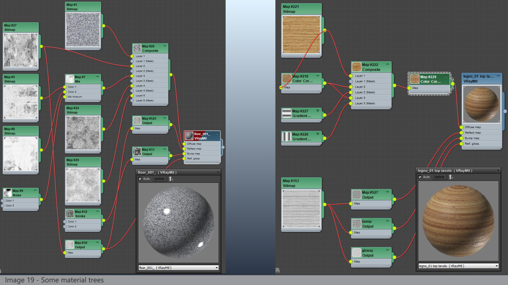
All the other shaders have been created as V-Ray materials, using maps for diffuse, reflection, glossiness and bump. Except for the diffuse channels, we normally use b/w maps; they always need color correction to get the needed aspect, and we did it directly inside 3ds max using output or color correction maps. This is very useful because we can have real time feedback without having to pass through other application, and we can also use one single map for reflection, glossiness and maybe bump, with different color correction in relation to different material slots.
We use the same trick to give some variations to the diffuse channel. A composite map with a base texture on the first layer, then one or two additional layers using the same texture with color correction, blended over the previous layers with a b/w masks or gradients. Some examples of this technique can be seen in the following picture, especially on the wood material.
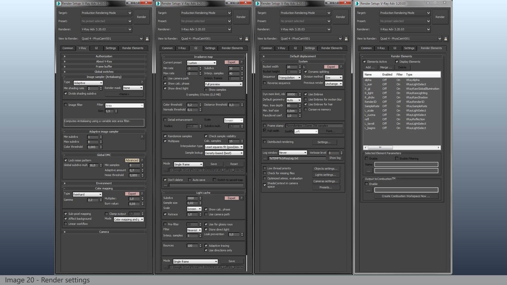
Rendering
The complete scene counted about 10.700.000 polygons, excluding all the scattered bricks. They all were V-Ray Proxies and counted about 54.000.000 polygons by themselves. So, in the end, there were about 64.700.000 polygons in the scene.
We rendered the final images at 2400x1600px, on a workstation with an Intel i7-3770K 3.50GHz CPU, NVidia GeForce GTX 570 graphic card and 16GB RAM.
We used Vray 3.20. Renderings has been a very hard task. Our goal was to obtain very high defined images, so we used very high render parameters. Render times took from 16 to 30 hours per image to complete, due to the complexity of the models (bricks walls generated lots of tiny details) and the presence of lots of glasses and other reflective surfaces.
We chose to output the final renderings as open .exr format file; this allowed us to save as many channels as we want in a single file, and this was pretty useful in the post-production phase.
Post-production
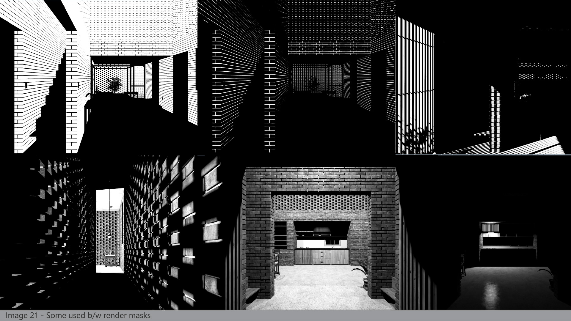
In our standard workflow, raw renders are quite different from the final images. And we do want this, because we strongly prefer to have flat images to start with (without extra-bright or extra-dark areas) so we can have useful color information for each pixel, and adjust every aspect in post production using a non-destructive approach (totally burned or underexposed areas in raw render are quite impossible to fix later). For this purpose we use AE and all the channels we exported from the render elements.
In particular, we used :
- Black and white masks to do selective color correction on bricks and mortar.
- The “light select” render element to boost artificial lights.
- The reflection pass to enhance them on the objects we feel too “flat”.
As final touches, aimed to eliminate some “fake CG looks”, we added to all the images some chromatic aberration, a very subtle vignette, a few glows and some flare effects on the light source.
We have resumed the main post production passes on a short breakdown, you can find it here.

Conclusion
That’s all! Thanks for your time spent reading this article, we hope you liked it. We tried to focus on the main aspects of this project without telling about very simple processes and other well known techniques we obviously used. If you have found something interesting we’ll be glad to know and if someone wants to have additional information just let us know in the comment section below!
See you soon!
Pixelpark.
Pixelpark is an Italian studio working in the field of 2D and 3D computer graphic. They are specialized in architectural pre-visualization and the main aspect of their work on which they focus the most is the photo-realistic look of the final images. Pixelpark strongly believes that a good pre-viz is a very efficient tool for architects and engineers to have a complete feeling of their projects.
Pixelpark previously published – Making of Los Faiques Dwelling


How can I make cross section like this in 3Ds? Or I have to use other softwares
If rendering with V-Ray you can use the VRayClipper feature – “VRayClipper is a geometric primitive that can be used to clip away parts of the scene with a simple plane. It is a render-time effect and does not modify the actual scene geometry in any way”. Otherwise a plugin like ScalpelMAX™ by Cebas that I recall of might help.
Ronen Bekerman – 3D Architectural Visualization Blog thanks,
So… who’s done bricks like this in some other interesting way?
What a great breakdown, thank you for taking the time to produce it – these things take a good amount of time and effort! Really nice imagery too, I love how there’s so many different ways for the sunlight to enter into the scene – through little gaps to the larger openings. Very atmospheric. Awesome work!
Fantastic breakdown, I sincerely I appreciate you providing such great detail. I’m curious why your exterior VrayPlaneLights are not set to Skylight Portal. I typically have a difficult time getting natural light into the space and instead get blown areas near the lights and dim interiors. I’d be very interested hearing your thoughts on this.
Thank you guys for your comments and appreciation words. And surely thanks a lot to you Ronen!
Ngo Phuongatula: as Ronen explained, we used Vray Clipper then using a “tech looking” materials on cut surfaces.
JohnnyPope: beside CG and arch-viz, we really like illustrations, animations and figurative arts in general, so when we finished this project (after months of spare time) we decided to “play around” with it some more weeks…
JaredFoley: we tried to explain our whole process in the clearest and more interesting way possible. Regarding arealights: we didn’t use Skylight Portal because we needed more freedom setting the different contributions, trying to mimic the reference pictures in which natural light is strongly influenced by the existing outdoor
Wow, that’s a very good
and detailed making of. Very interesting read. Especially like the
plants creation part, and the Bricks of course. I’m not a vray 3dsmax
user, but one thing.. your global subdivs mult. is at 16! Never
thought that I could go so high 😀
Phil Buerer Thanks Phil for your words. Yes, 16 is a very high number for the global subdivs, but it has been necessary. We set our materials with 32 samples, so 32*16=512 samples for the shaders, and this was (by experimenting) the min value to eliminate every grain from blurry materials. Any smaller value would have introduced grain and this would have even been enhanced in post using contrast and other effects.
Cheers!
pixelpark Phil Buerer Hi “pixelpark”, first of all I’m very impressed by the beautiful scene and renders. It’s always nice to see how other people make great images like these. Though I am suprised by your rendersettings as these seem imbalanced and I expect you could get equal quality or better in less time with some optimisation.
You write you were having trouble with grainy blurry reflections and solved them by increasing the global multiplier to 16. This actually lowers the benefits of the adaptive image sampler alot. What I would suggest is setting the global multiplier to 1,the minimal shading rate to 6 and the max subdivs in the adaptive sampler to 32. This will give Vray the ability to keep sampling grainy parts of the image instead of forcing it to sample the total image to very high levels, even in places where it would not be needed.
Anyway, keep up the good work, posts like these are always an inspiration! 🙂
kerel thanks for your appreciation words and surely for your suggestion. From time to time we return to tutorials and we test Vray settings to optimize quality/render time balance… and honestly we don’t fell at the end of the path! And surely we’ll go back to it again 😉
Wow!! What an incredible ´Making of´!!
First of all I want to apologize for my poor english, I hope yo can understand what I’m saying.
I’m trying to achieve similar brickwalls but I’m having problems with setting up the UVW Mapping for my distribution plane… could you explain how do it properly?
Thanks!!!
eduvingis Hi and thanks!
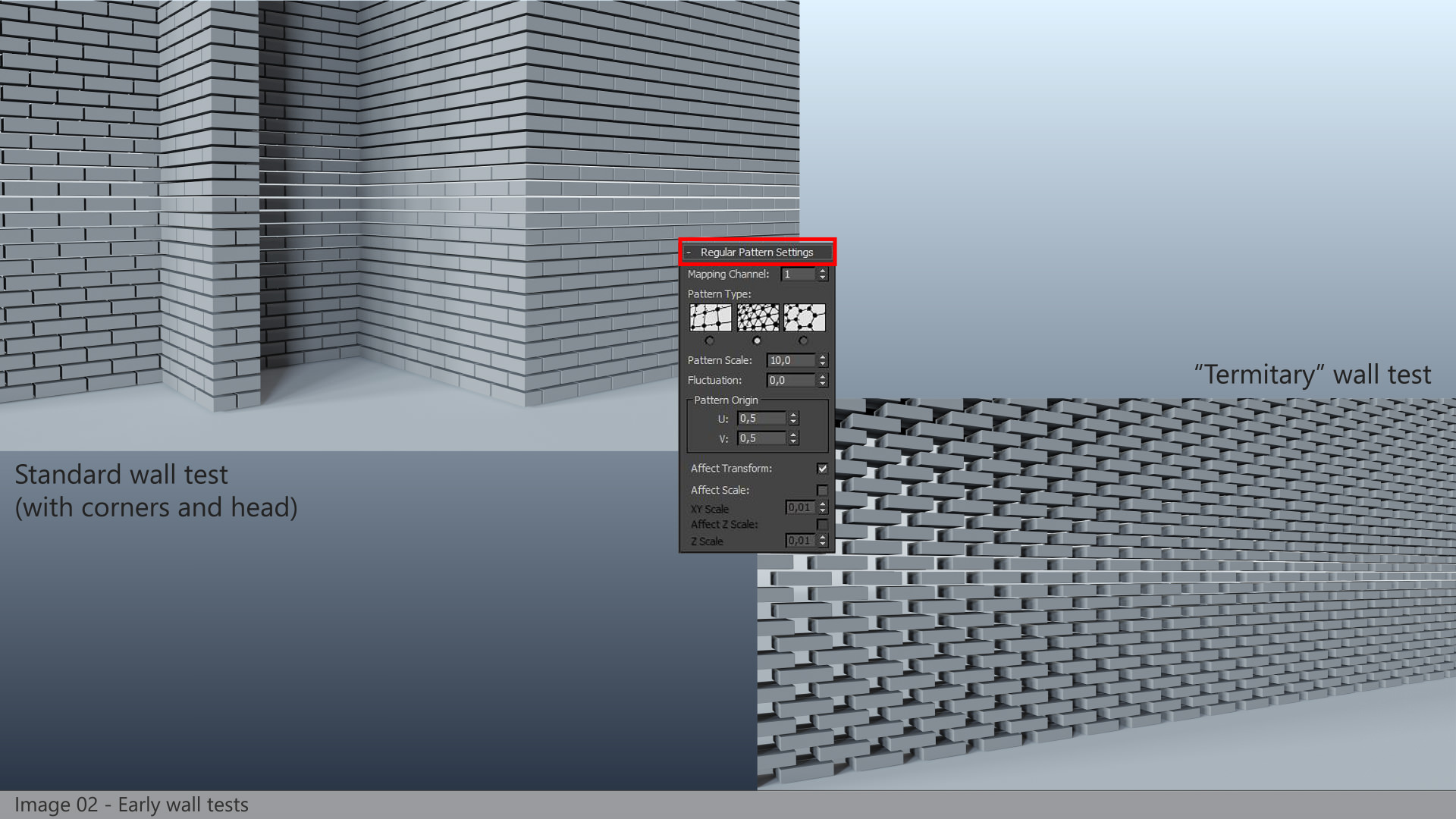
For multiscatter regular distributions, really there’s not much more to add, but I try.
You can refer to image 02 for multiscatter settings. Then you have to apply a UVW mapping set to box to the distribution object (a plane in our case) and then play around with U, V, W values until you obtain the desired result.
Keep us informed, if you like 🙂
pixelpark eduvingis Thanks!! Finally I achieve muy objective!!
Happy! 🙂
Wow!! What an incredible ´Making of´!!http://goo.gl/DoKFzg
3D animation is a great way to tell a story, to describe a service or to visualize a particular product or process without the constraints and limitations of reality holding you back. Our strength lies in developing photorealistic renderings of the un-built and built environment through still renderings, walk-throughs and fly-by animations, virtual tours, panoramic renderings, photomontages and 360 degree interactive videos.
For more details click here-